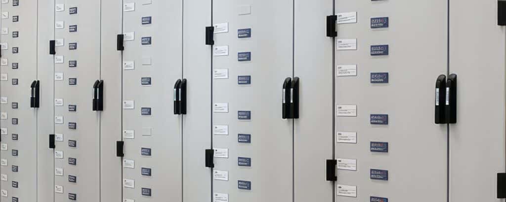
MODUL-K-425-SYSTEM
Low-voltage power distribution unit with type verification for the highest constructional and technical demands in a compact design with a 425 mm panel depth.

With the MODUL-K-425-SYSTEM, we have developed a technically high-quality and structurally optimized system for low-voltage switchgear. Its reduced panel depth allows space for what’s essential at the installation site. The modular plug system enables the exchange of modules under voltage, thus ensuring high availability of your facilities.
Technical Data
Standards and Regulations
Type Verification
DIN EN (IEC)61439-2,
DIN VDE 0660-600-1+2
Protection Against Touch
DIN VDE 50274,
DIN VDE 0660-514
Arc Fault Testing
IEC 61641,
DIN VDE 0660-500 Supplement 2
Air and Creepage Distances
Rated Impulse Withstand Voltage (Uimp)
12 kV
Overvoltage Category
III
Pollution Degree
3
Rated Insulation Voltage
1000 V
Rated Operating Voltage
690 V
Busbars E-CU-F30
Main Busbar
1250 A to 2000 A
Surface
Bare (coating optional)
Cross Section
50% PE (PEN)
100% N (optional)
Rated Peak Withstand Current
Ipk to 162 kA, 0,1 sec
Rated Short-Time Current
Icw up to 68 kA, 1 sec
Electrical Main Components
Open MCCBs
up to 2500 A
Compact MCCBs
up to 1600 A
Fuse Switch Disconnector
up to 630 A, Size 00 / 1 / 2 / 3
Motor Relays
Thermal / electronic /Fieldbus
(Industrial Ethernet ready)
Motor Starters (IEC 60947-4-1)
Coordination Type 1 or 2
various Typicals
Internal Segregation
Form 2b to Form 4b
IEC 61439-1
Metal
Frame
Stainless steel
Doors, Side Panels
Powder-coated
Internal Support/Partition Plates
Sheet metal
Protection Type
IEC 60529 / DIN 40050
IP 31 (up to IP 54)
Environmental Conditions
DIN EN 60947-1 / 61439-1
Min. -5°C, max. +45°C,
35°C over 24h average
Dimensions
Height
1800 / 2000 / 2250 mm
Panel Width
600 / 900 / 1000 mm
Panel Depth
425 mm
All mentioned rated currents are nominal values and manufacturer specifications. Depending on the installation condition and environmental conditions (such as IP protection class, ambient temperature, etc.), a reduction in load capacity must be considered.
Feeder and Outgoing Fields
Feeder Fields
with compact circuit breaker (up to 1600 A);
with open circuit breaker (up to 2500 A)
- Fixed mounting and plug-in technology, 3- or 4-pole
- With segregated metering niche
- Separate cable connection compartment for optimal connection conditions
- Access from above or below
- Safe switching of the circuit breaker with the door closed
- Tested installation position of the surge arrester
- Energy metering stations (optional with bus technology)
with compact circuit breaker (up to 1600 A);
with open circuit breaker (up to 2500 A)
- Fixed mounting and plug-in technology, 3- or 4-pole
- With segregated metering niche
- Separate cable connection compartment for optimal connection conditions
- Access from above or below
- Safe switching of the circuit breaker with the door closed
- Energy metering stations (optional with bus technology)
with NH fuse load switch strips
- In hole-less fixed mounting technology from 125 A to 630 A (Size 00 /1 / 2 / 3)
- With optional metering niche for measuring devices and small outgoing circuits
- Cable outgoing with or without measuring devices and meters
- Generous cable connection compartment
- Hole-less connection technology
in plug-in technology
- from 125 A to 630 A (Size 00 – Size 3)
- 3- or 4-pole execution
- Segregated busbar system
- Supply and exhaust air system for field load up to 1800 A
- Access from above/below simultaneously possible
- Cable outgoing with or without measuring devices and meters
in modular technology
- Up to 400 A (630 A)
- Internal segregation according to Form 4b
- 3- or 4-pole execution
- Segregated busbar system
- Field load up to 2000 A
- Side cable connection compartment 400 mm, optional 600 mm
- Access from above or below simultaneously possible
- Cable outgoing with or without measuring devices and meters
- Fixed mounting and plug-in technology combinable
- Freely combinable module plates
- Circuit breaker outlets
- Motor outlets
in modular plug-in technology
- Internal segregation according to Form 4b
- 3- or 4-pole execution
- Segregated busbar system
- Supply and exhaust air system for field load up to 1800 A
- Access from above/below simultaneously possible
- Freely configurable plug-in module
for small consumers
- Cable outgoing above and below possible
- Device compartment with metal covers
- Freely configurable device compartment
Further Details
- Highest plant safety and personal safety through type verification (TSK) and arc fault testing (various manufacturer brands tested)
- Own development and design with continuous further development and adaptation to market situations
- Expandable in all versions due to standardized dimensions
- Pre-prepared installation spaces for all built-in devices and expansion parts
- High-quality and solid construction for industrial applications with few system components, for the highest plant availability, in modern industrial design
- Flexibility also for customer-specific special solutions
- Several patented detailed solutions such as: busbar system, multifunctional strut rail connections, MCC contact switches
- Consistent further development of the hole-less connection and joining technology up to the PE/PEN/N rail
- Manufacturing on CNC-controlled laser machines and press brakes
- Switchgear frames in stainless steel, rust-free without painting
- Internal subdivision up to Form 4b for circuit breaker panels, switch fuse strip panels, and MCC fields (Motor-Control-Center)
- Circuit breakers prepared for parallel cable connection
- Cable/rail connection from above or below possible
- Optional rail distributors from the transformer to the switchgear
- Cable management distributor with integrated cable tray and cover panels for cable entry from above
- Compensation systems in module insertion technology with automatic fan control for long lifespan
- Multiple variable busbar positions
- Uniform busbar system, expandable on both sides within the shortest shutdown times (approx. 20 min.) through new hole-less busbar connection
- Trouble-free retrofitting of switching devices through hole-less connection technology
- Trouble-free retrofitting of current transformers into NH strips
- Dirt-repellent design head strip
- Integrated switchgear base
- Corner switch panel is possible as a system solution